Customized Escort 360 SmartCord Install // 02.09.2018
|
I never did feel great about my version 1 of a remote mute switch. It was nowhere near as practical and stealth as my old RS4 or even B5 S4 solution. For the RS4, and old friend had developed a remote switch for the Valentine 1 that I had at the time which I wanted to reproduce for this. I hadn't seen any advertisements on ebay or otherwise for similar products for the Escort 360 so I decided to purchase an extra SmartCord cable and see what I could do.
First, here are all of the things I used for this project:
There are 3 small phases to this: |
|
Modify the existing housing...
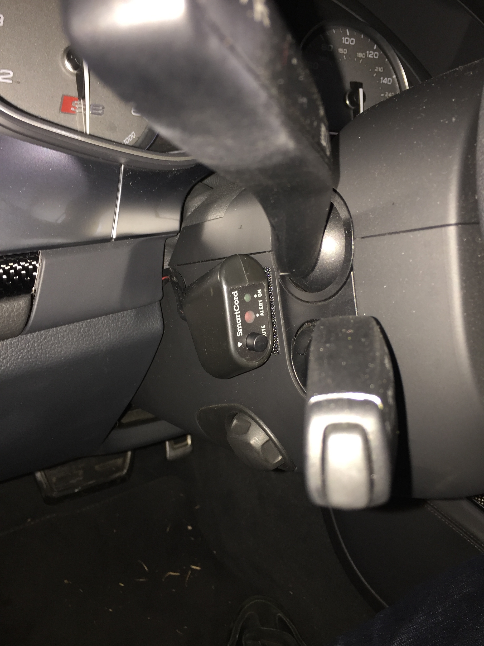
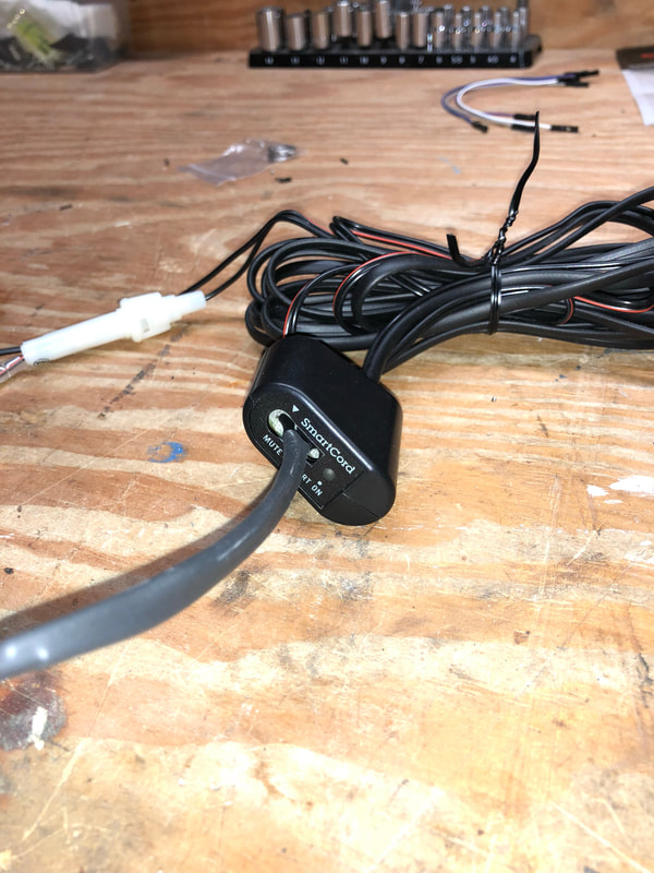
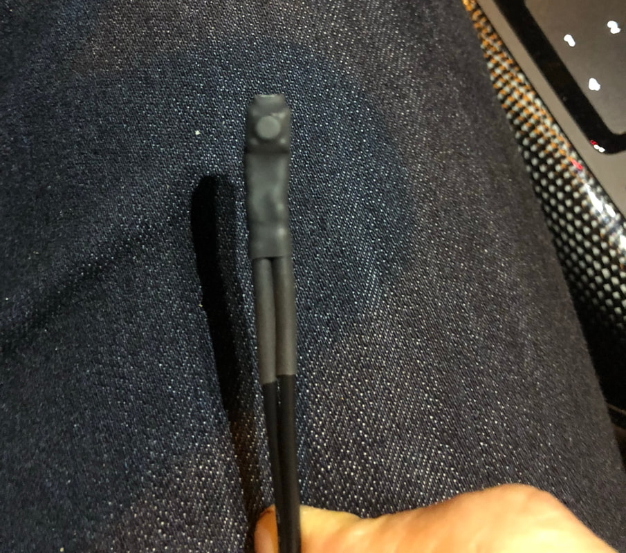
Below left is the SmartCord cable as it comes, and as I had installed prior to this project. While it was a step better than reaching up to the radar detector itself, it was nowhere near as convenient as the old setup. Note it has the mute button on top, and also an 'On' LED (green) and a warning LED (red).
There's one screw that keeps this piece together. Take that out and separate the shell (you have to peel back the sticker that has the 'SmartCord' and other labels on it) and below right is what you have...a pretty simple PCB.
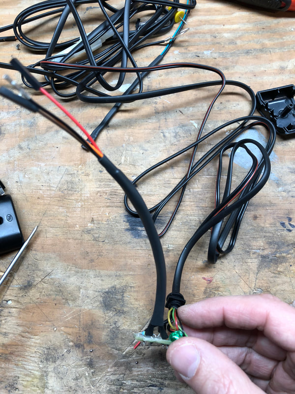
The plan was to desolder the mute button and the red LED, then solder on wire leads to which I'd put a new, smaller mute button and a new LED onto.
There's one screw that keeps this piece together. Take that out and separate the shell (you have to peel back the sticker that has the 'SmartCord' and other labels on it) and below right is what you have...a pretty simple PCB.
The plan was to desolder the mute button and the red LED, then solder on wire leads to which I'd put a new, smaller mute button and a new LED onto.
|
|
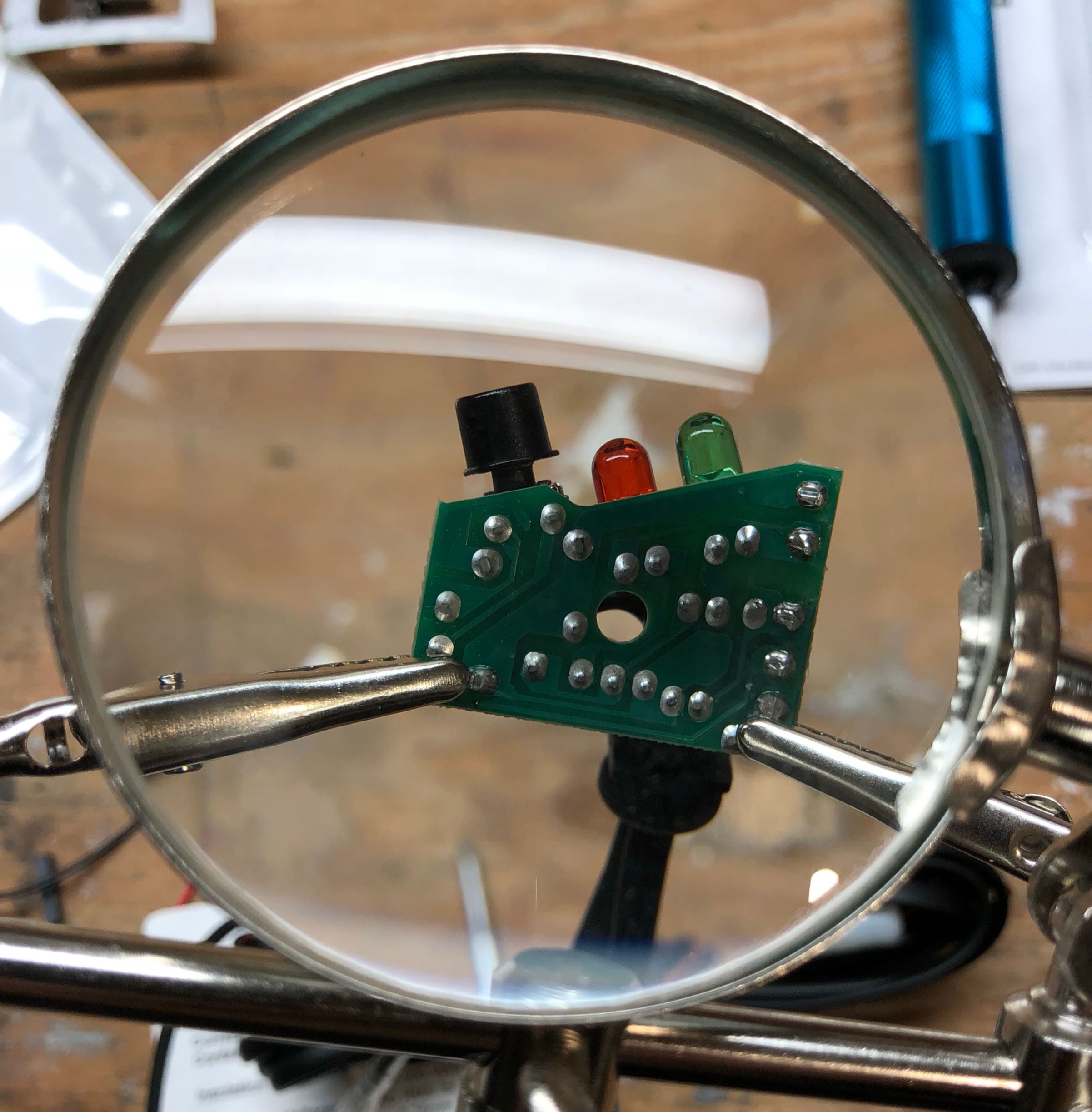
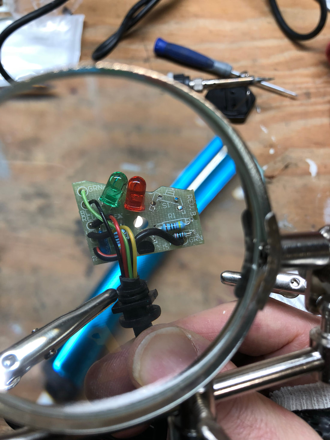
Desoldering the mute button complete below, using the 'helping hand' magnifying glass setup. To desolder, heat up the solder with the gun on the back side of the PCB (i.e. not the side pictured), and when it bubbles, pull the trigger on the gun to suck up the solder. I had to repeat this a bunch of times to get it all out as it's pretty hard to get the solder vacuum right where it needs to be. So, it's not an awesome way to do it (much prefer an actual desolder gun) but the price is right.
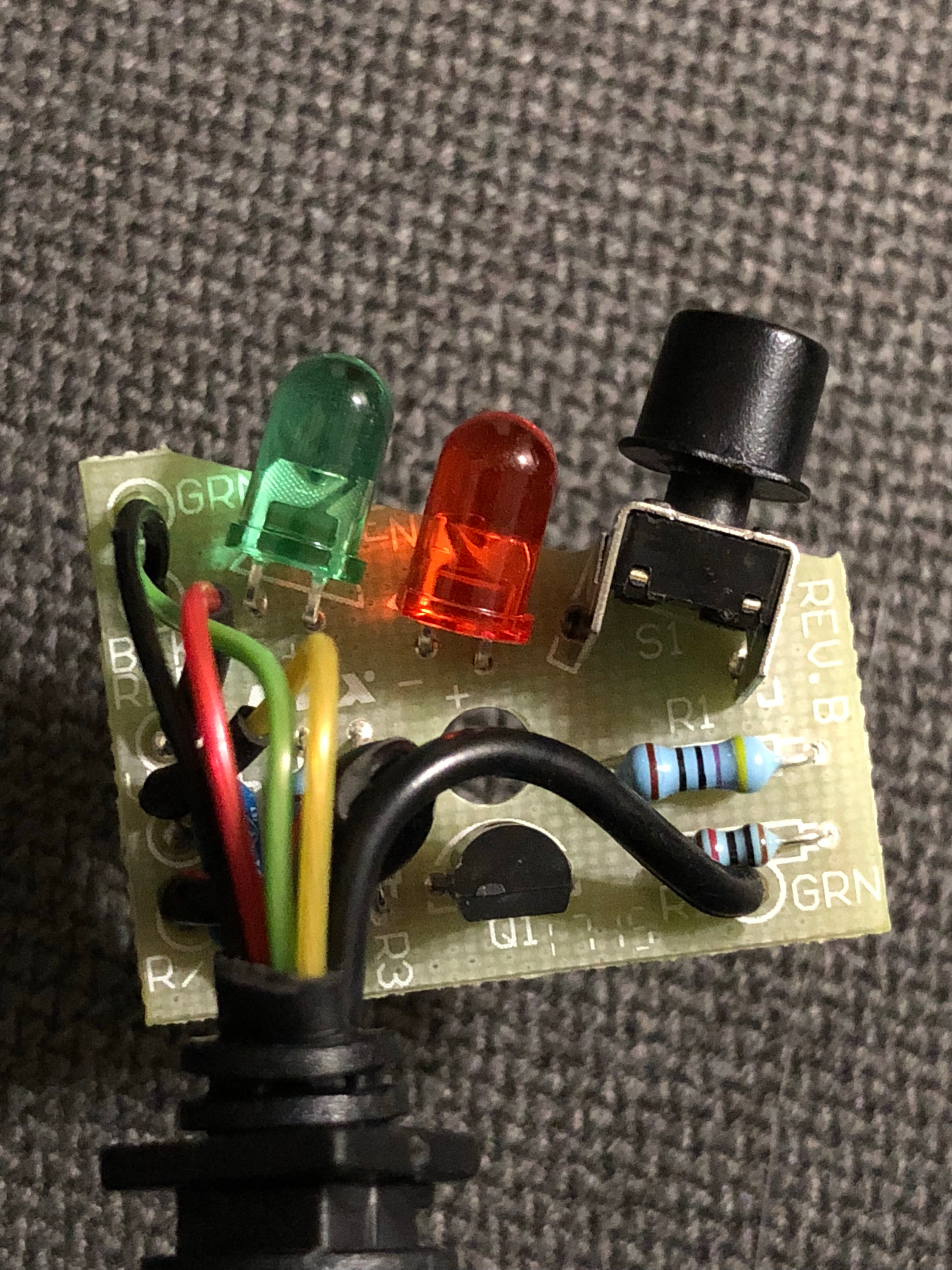
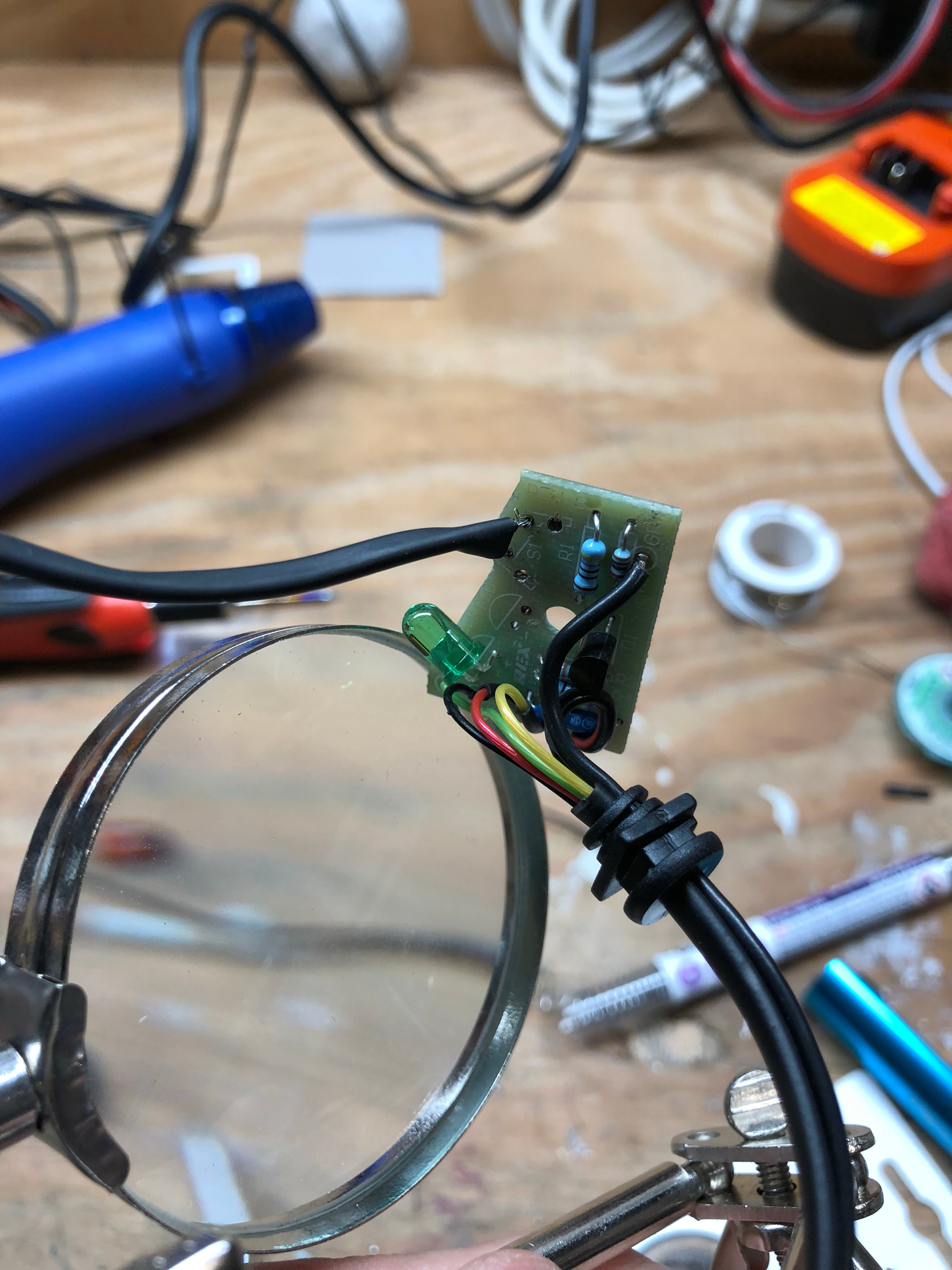
Didn't get a pic of them both desoldered, but below you can see the red LED is gone now, too, and I've already soldered on wires for the mute button extension and used heat shrink on top of them. As with removal: solder on the back side of the PCB. In center, below, you can see the red LED is gone now, too, and I've already soldered on wires for the mute button extension and used heat shrink on top of them.
Didn't get a pic of them both desoldered, but below you can see the red LED is gone now, too, and I've already soldered on wires for the mute button extension and used heat shrink on top of them. As with removal: solder on the back side of the PCB. In center, below, you can see the red LED is gone now, too, and I've already soldered on wires for the mute button extension and used heat shrink on top of them.
|

|
|
|
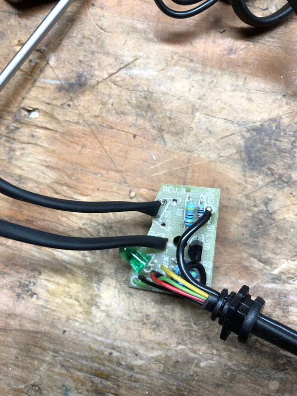
Above right: for the wire that attaches to the PCB, I used some PC wires I had laying around, the kind you usually use for on/off motherboard connections. Those 4 wires then all heatshrunk together, the center of the sticker cut out, and the shell put back together:
Time to make the mute button...
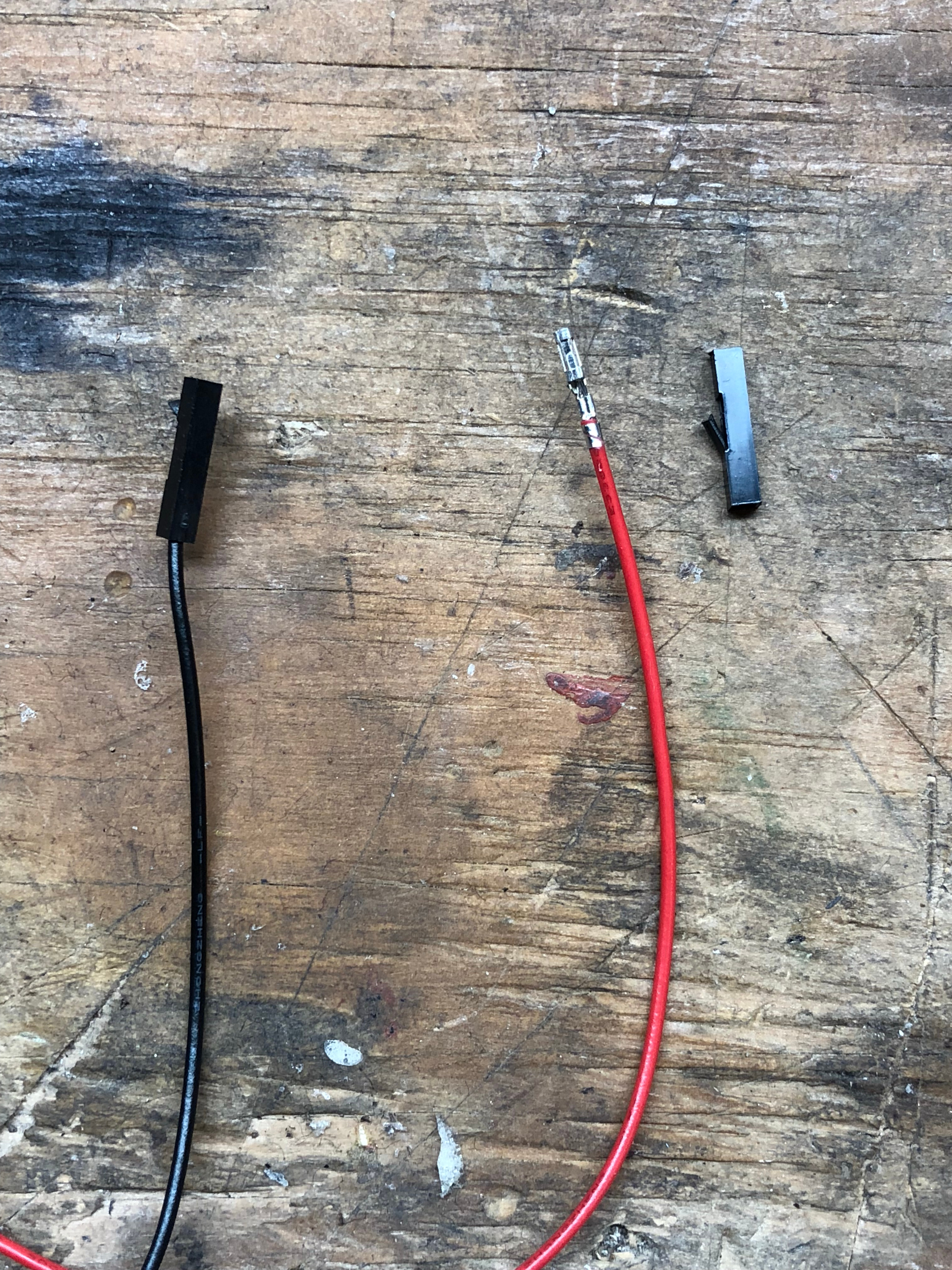
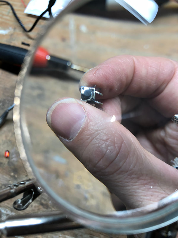
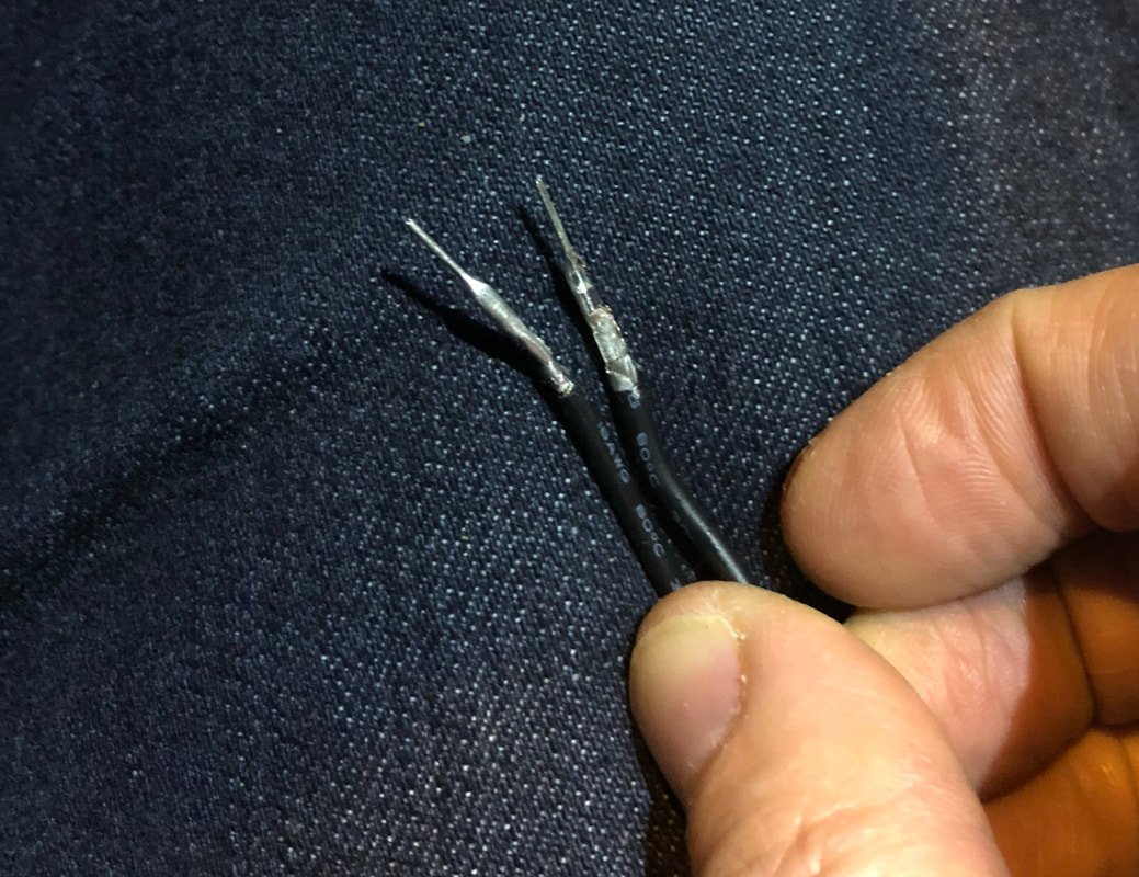
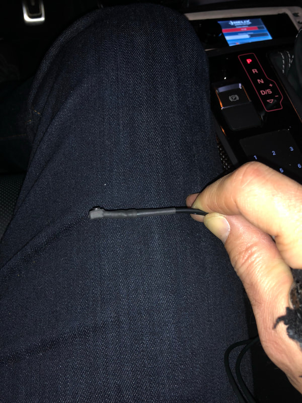
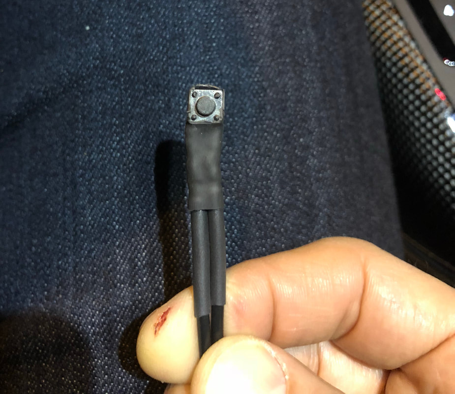
With the housing done, I went ahead to make the remote button with cables. For this I used a 6mm x 6mm momentary tactile switch that I picked up at ye old Fry's Electronics in the area. They come with 4 pins, and I only needed to use 2 of these. The other 2, I just twisted off. To connect wire to the two remaining ones, I crimped on the pin connectors, put heat shrink around each once slid into the button's pins, and then put a bigger piece of heat shrink around the whole button, too, after which I cut away some to expose the face of the button.
Finally, installing...
Now, just need to put it all together. First, remove the driver's side fuse panel cover, then remove the knee bolster (3 13mm bolts, one on the left by the fuses, two on bottom side of knee bolster). As per my write-up on the ALP install, if it's the first time taking knee bolster off, you're in for a treat: just pull as hard as you can...you'll get it off...eventually ;)
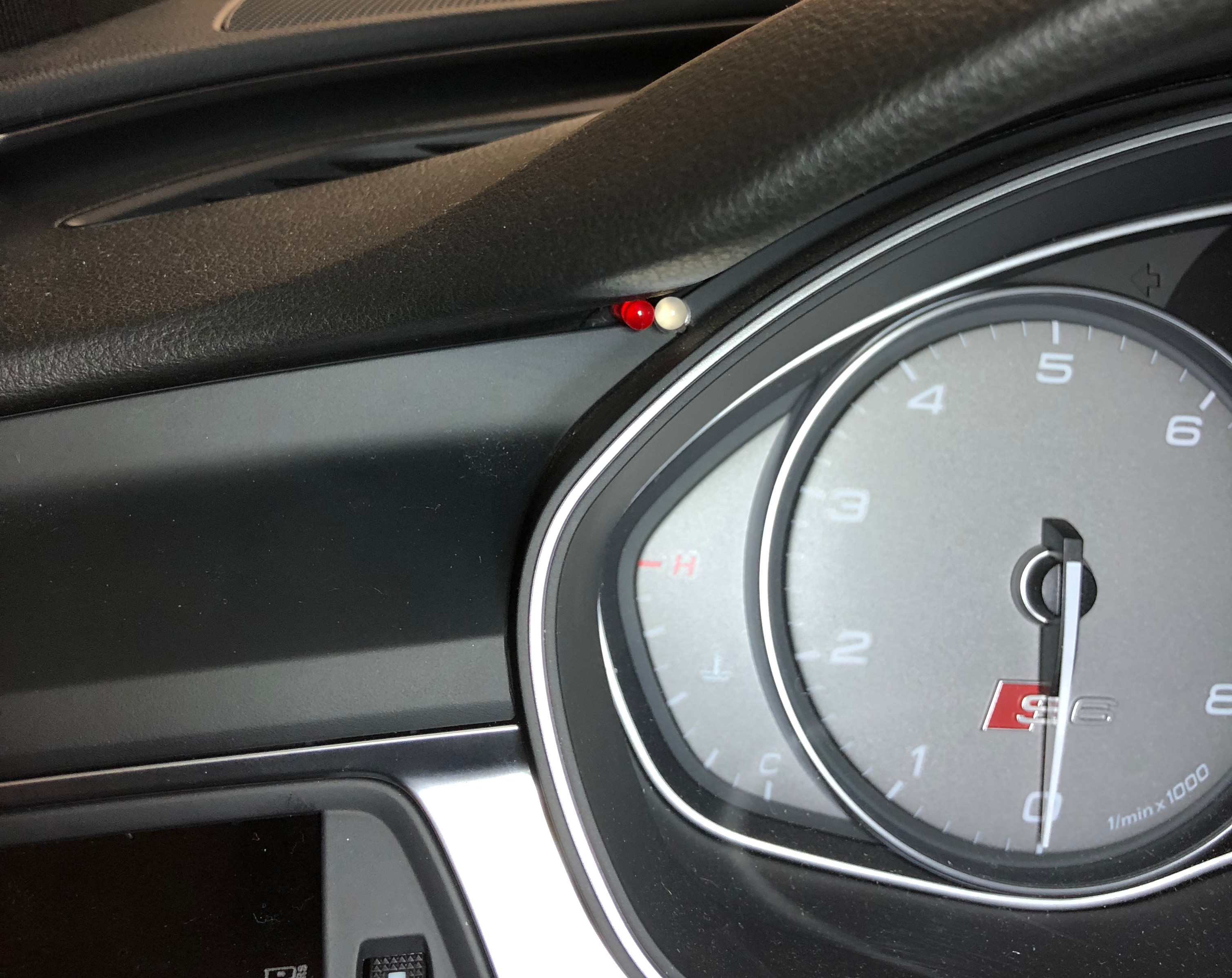
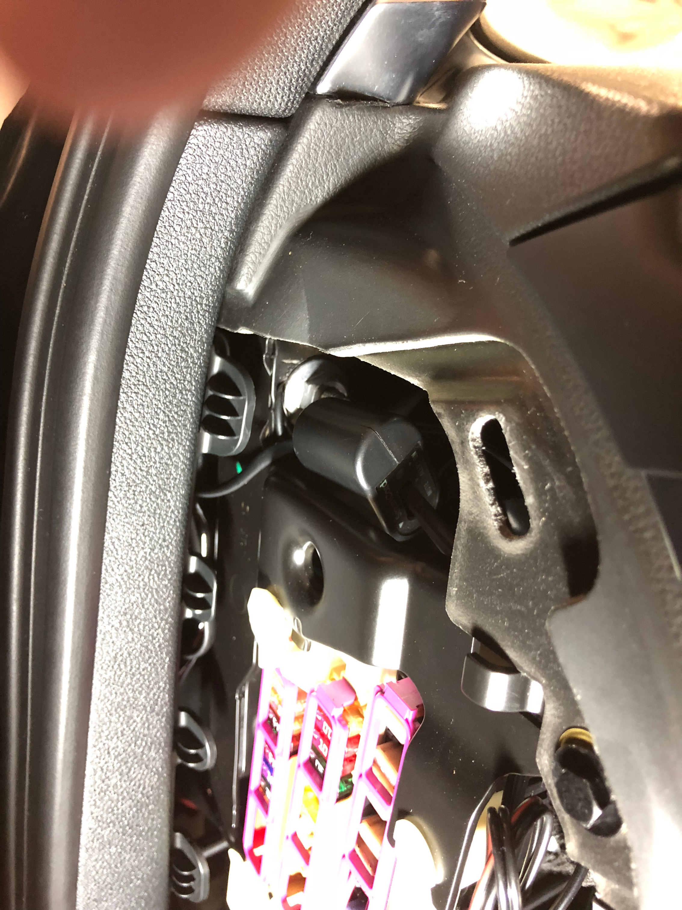
Next, take off the dash trim above the left vent. It easily pulls off left to right (see the first 10 seconds of this P3cars video for details ). Next, I routed the LED light and cable. For the LED itself, you can squeeze it into position rather easily, and guide the wires to come out in the location below left. LED in position below right, with the trim panel back in place. The LED to the right you see is from my ALP install.
Next, take off the dash trim above the left vent. It easily pulls off left to right (see the first 10 seconds of this P3cars video for details ). Next, I routed the LED light and cable. For the LED itself, you can squeeze it into position rather easily, and guide the wires to come out in the location below left. LED in position below right, with the trim panel back in place. The LED to the right you see is from my ALP install.
|
|
With the LED set for now, time to put the mute button into place...
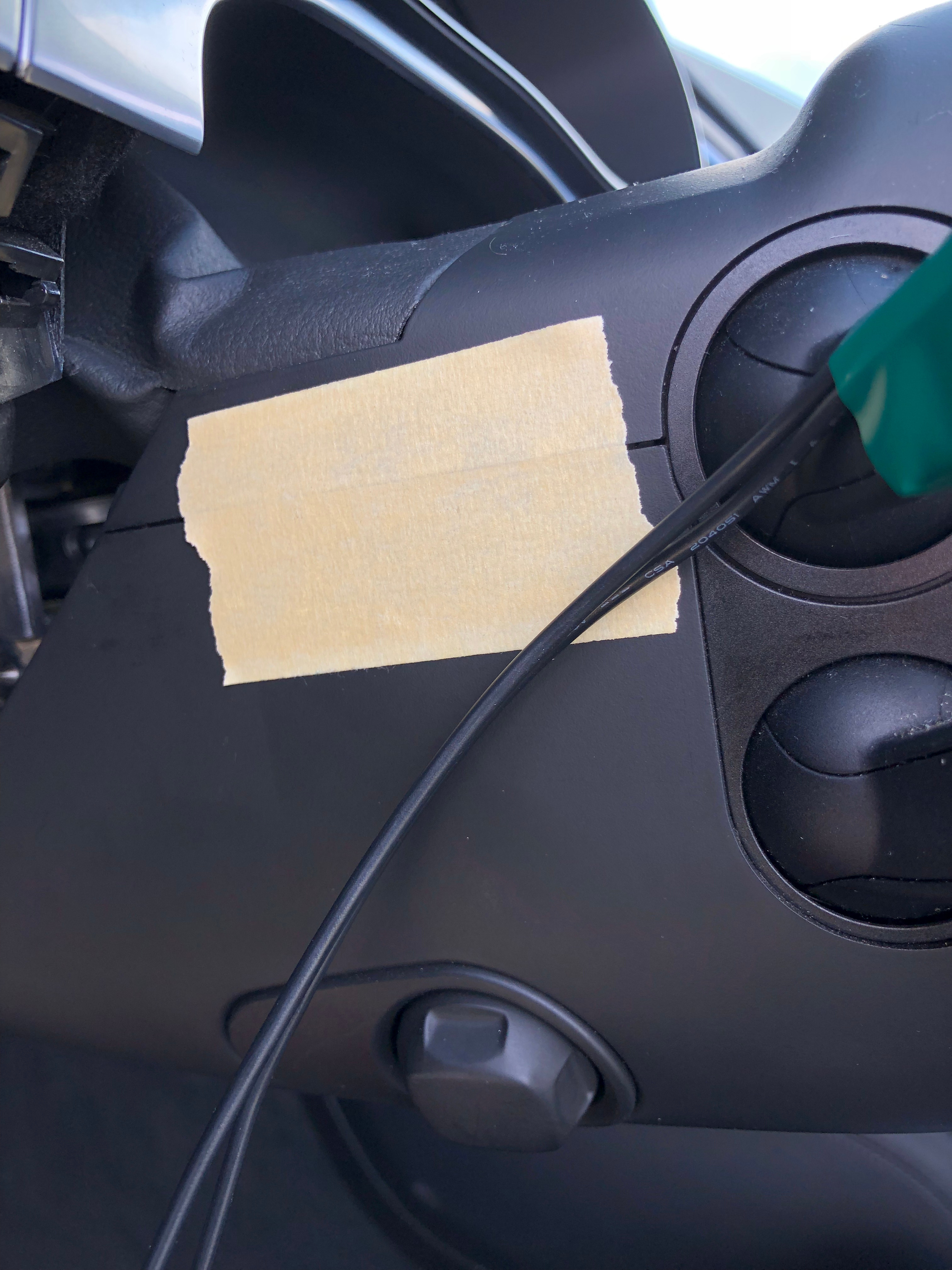
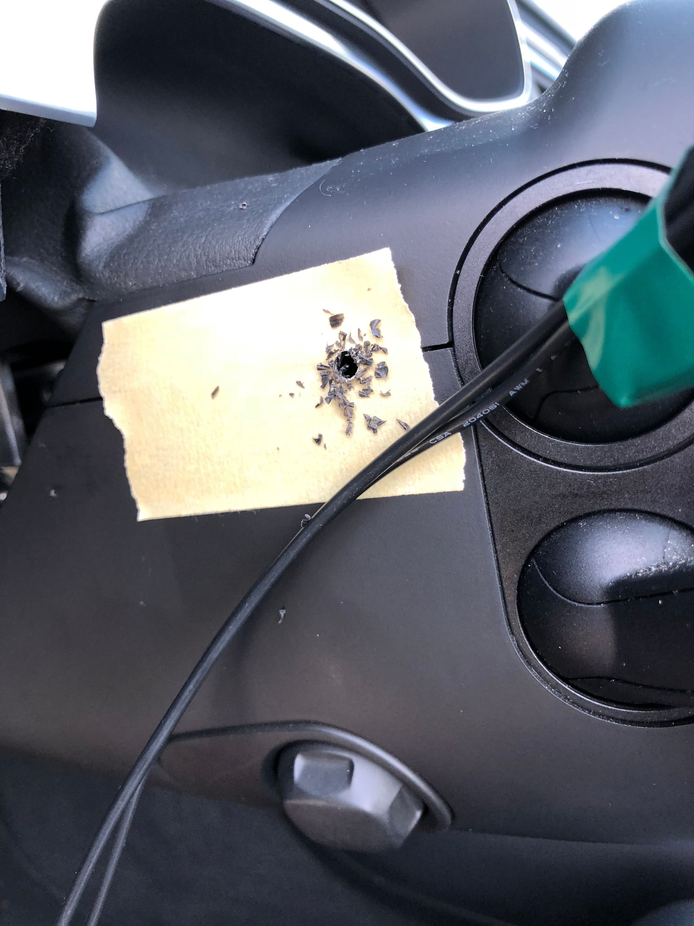
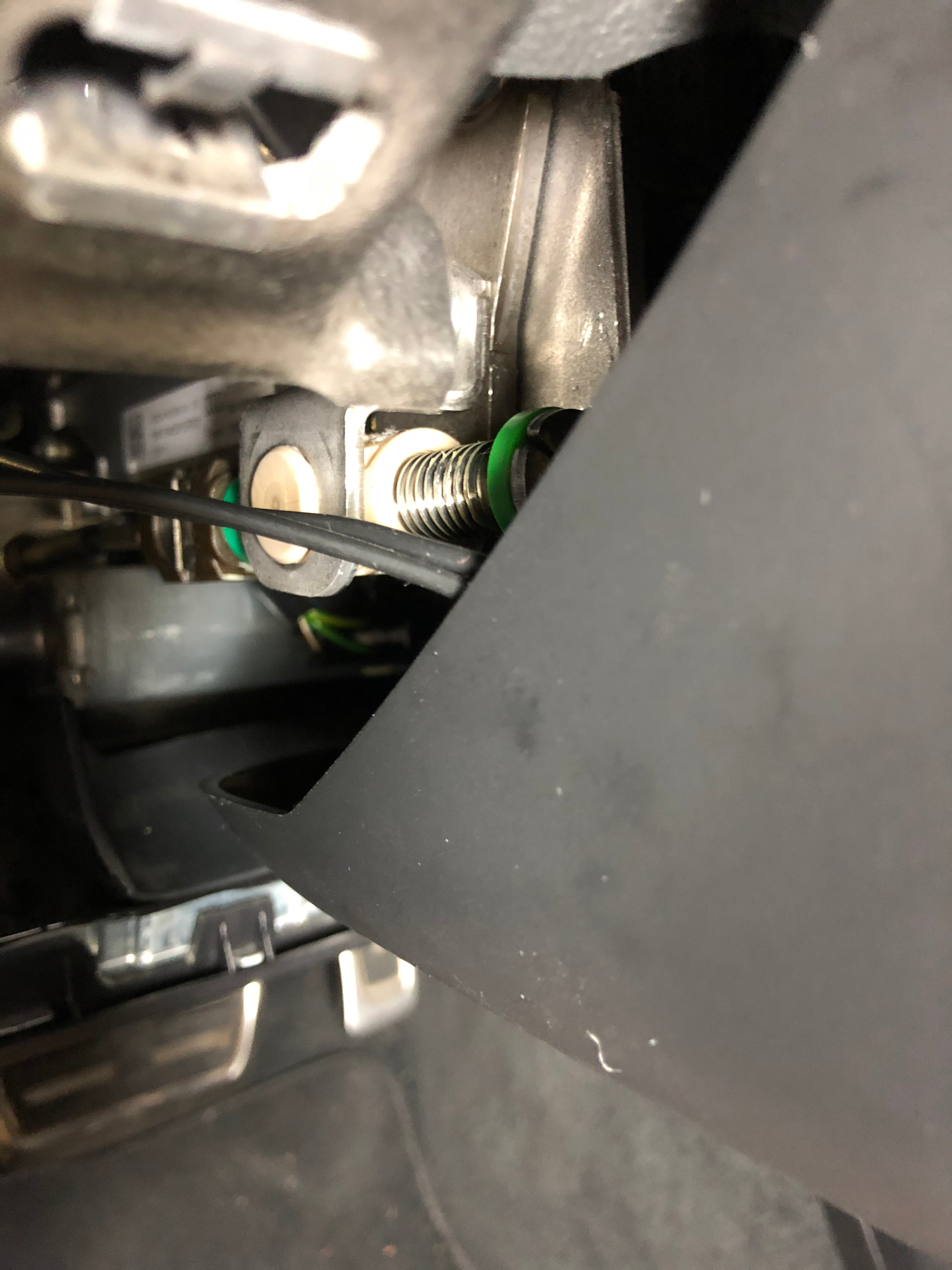
A hole needs to be drilled, and best place is right on the seam between the upper and lower steering column covers. There's nothing behind it in this area, so no worries on hitting something. I add masking tape to make sure the bit doesn't travel. I used an 11/64th's bit.
A hole needs to be drilled, and best place is right on the seam between the upper and lower steering column covers. There's nothing behind it in this area, so no worries on hitting something. I add masking tape to make sure the bit doesn't travel. I used an 11/64th's bit.
|
|
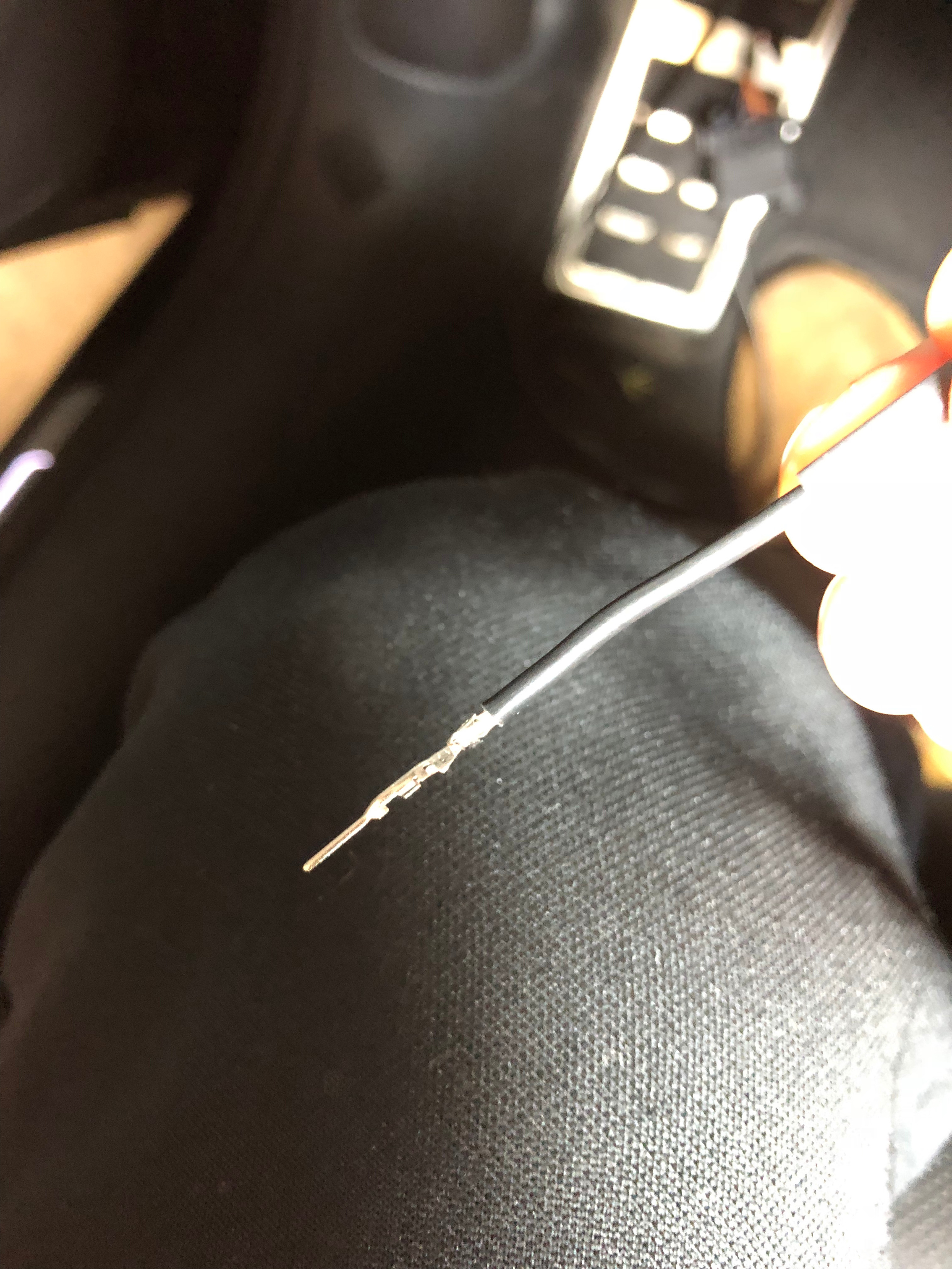
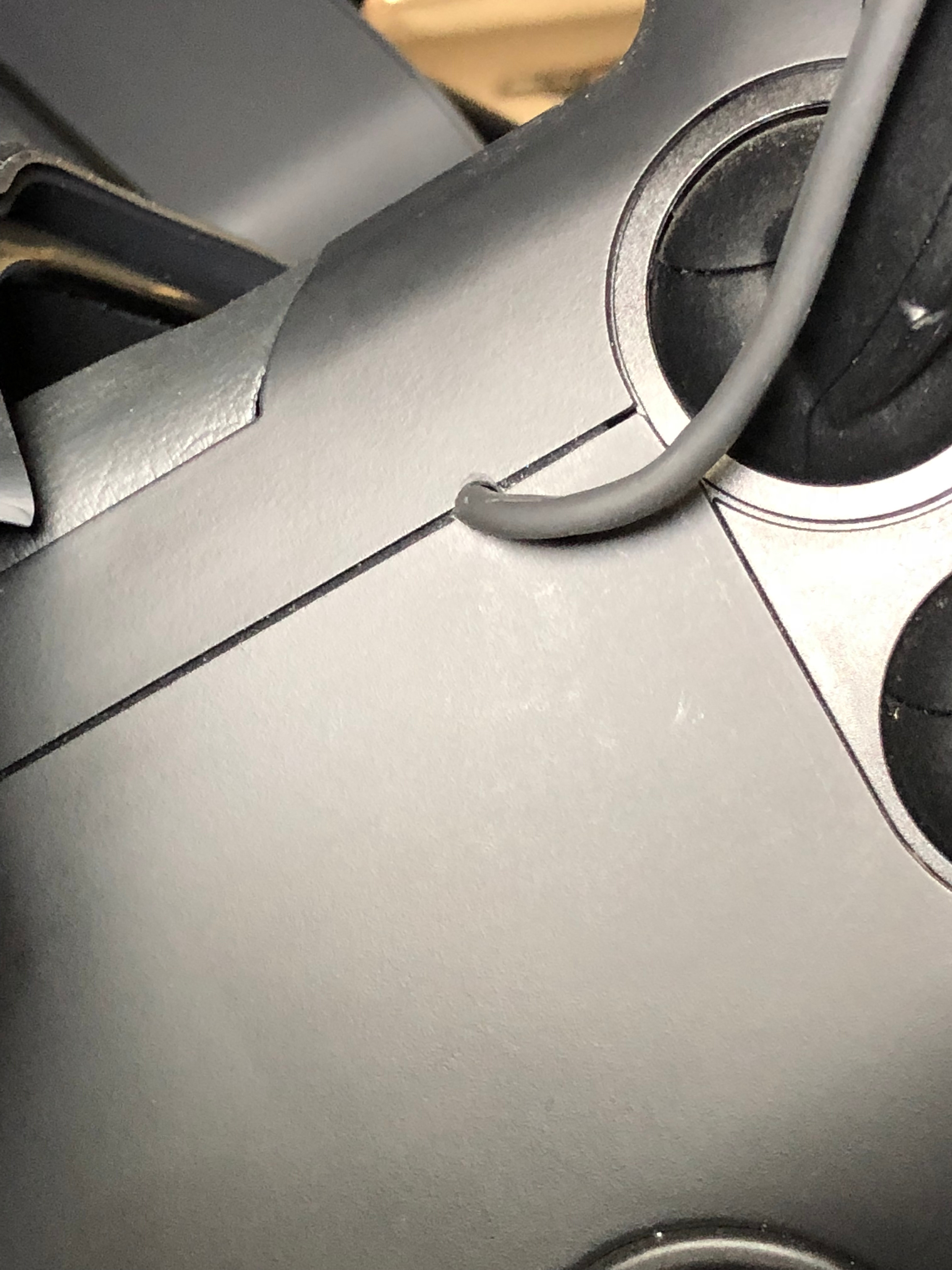
Put on some heat shrink prior to feeding the wires through, then crimp the connectors to the ends. To make sure the cables inside the steering column don't interfere with anything, I put 3M double-sided tape over them and taped them to the left side of the column cover. Heat fun to the heat shrink and we're almost there.
|
|
|
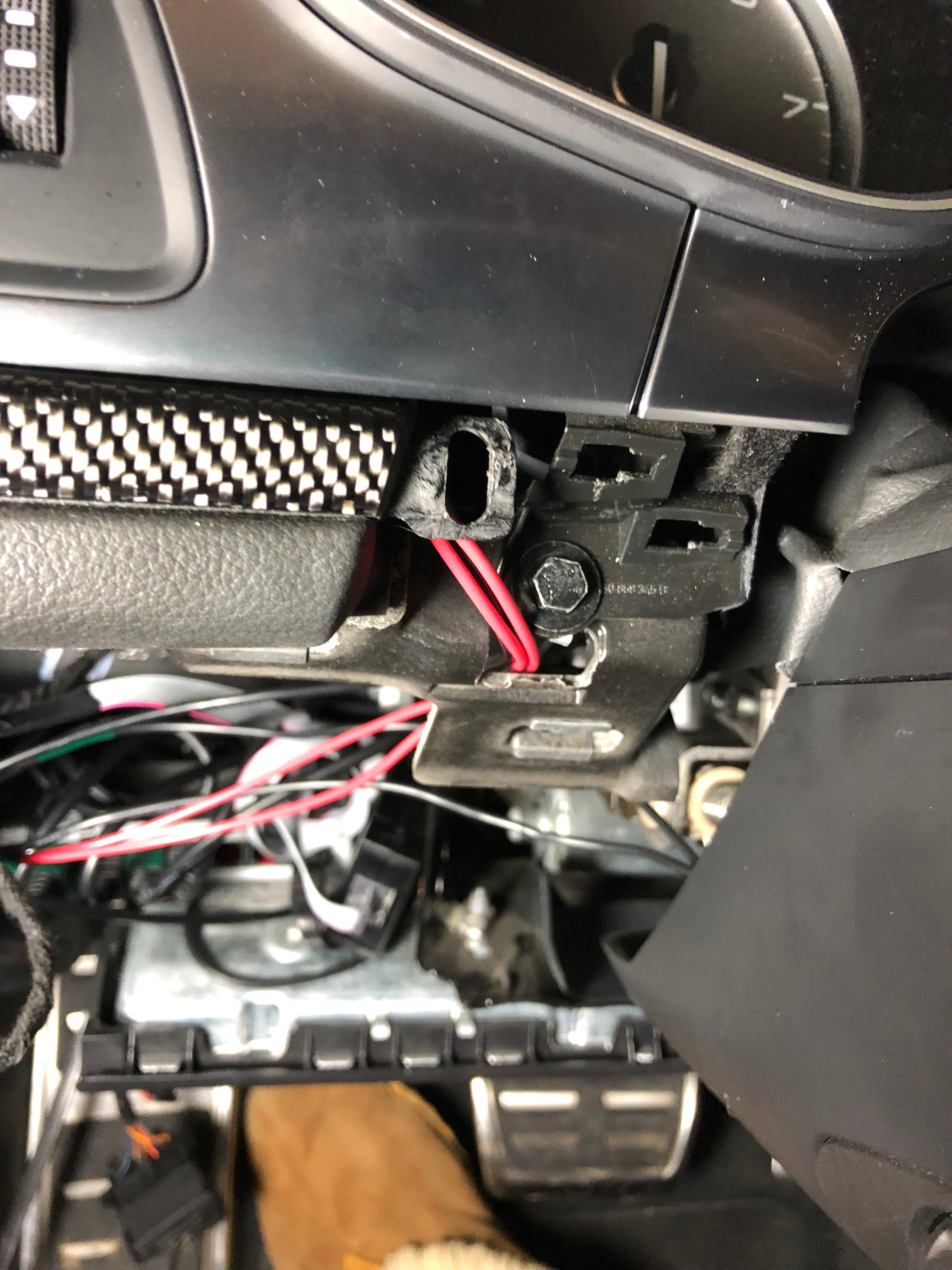
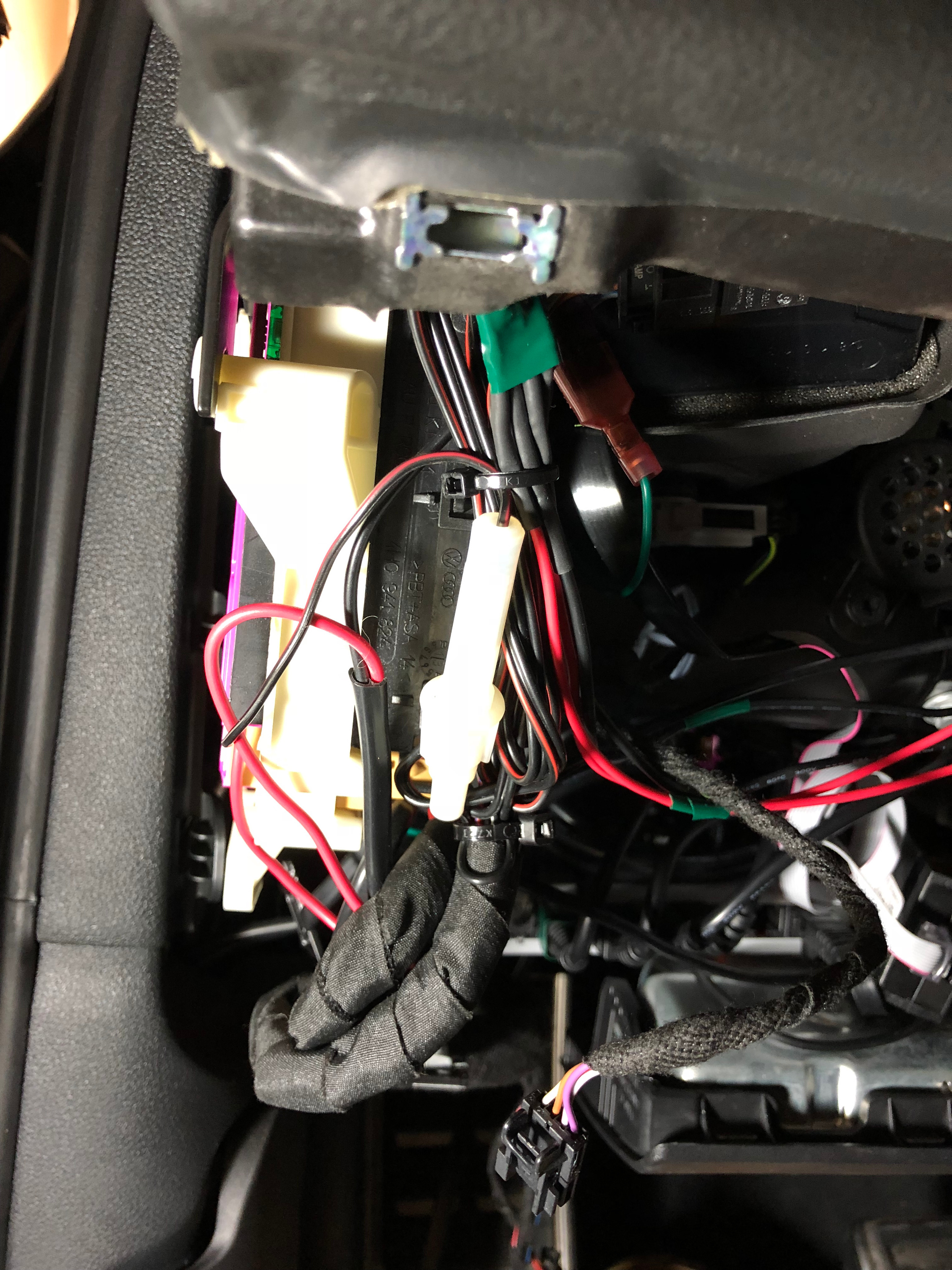
I routed the cables through the same area as the LED ones, then plugged them into the wires from the modified housing, adding heat shrink here also so that they stay in place, but if need be, can be disconnected. Zip tied to existing wiring near the fuses and there's enough slack in the wiring so that when I put the knee bolster back on, I gently lift the wires above the foam piece on the bolster. The modified housing rests snugly atop the fuse panel (note, I don't cover the cable routing for power or to the detector here as that's documented on the main Escort 360 page).
|
|
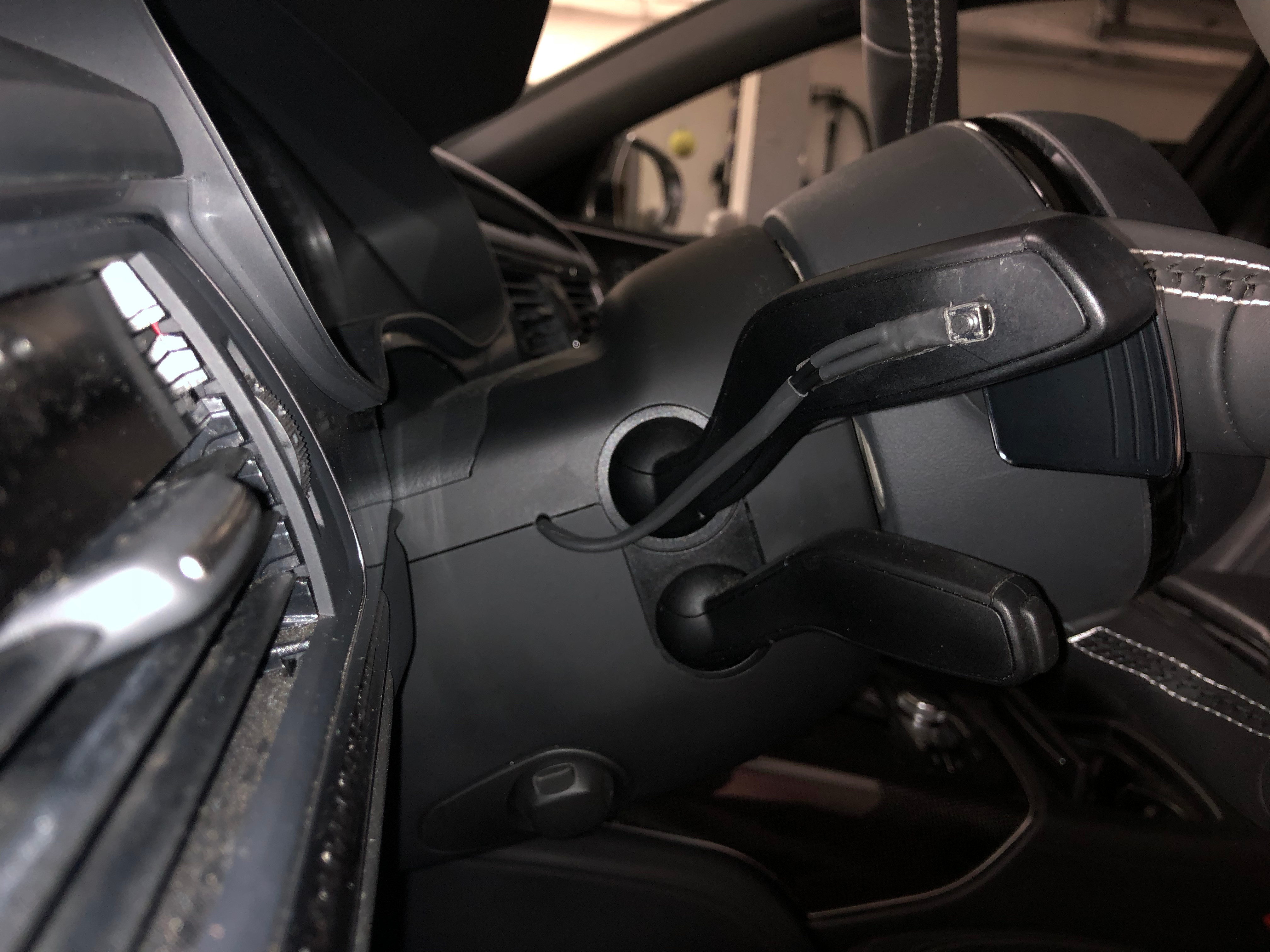
The finished product...when an alarm goes off, I now see the red LED much better from this PoV compared to the radar detector itself, and if/when I want to mute the alert, all I have to do is extend my middle finger (ha!) without changing my grip on the steering wheel. Fun stuff.