ALP: Rear Sensors Install //01.10.2016 |
|
The last part of the install, and there are a few steps to it.
Thanks to a fellow AZ member, I learned that you can route the cable for the sensors through by the tail light. Note, you will need to order the extension cables from ALP otherwise you will end up about 18" short! With that in mind, I figured out how to disassemble the inside of the trunk lid, and the interior left side of the trunk so that I could route my cables that way.
|
|
First things first, trunk lid disassembly, which is as follows:
|
|

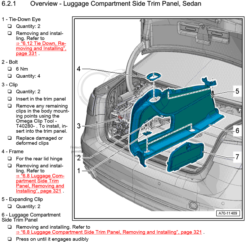
Steps 4 and 5
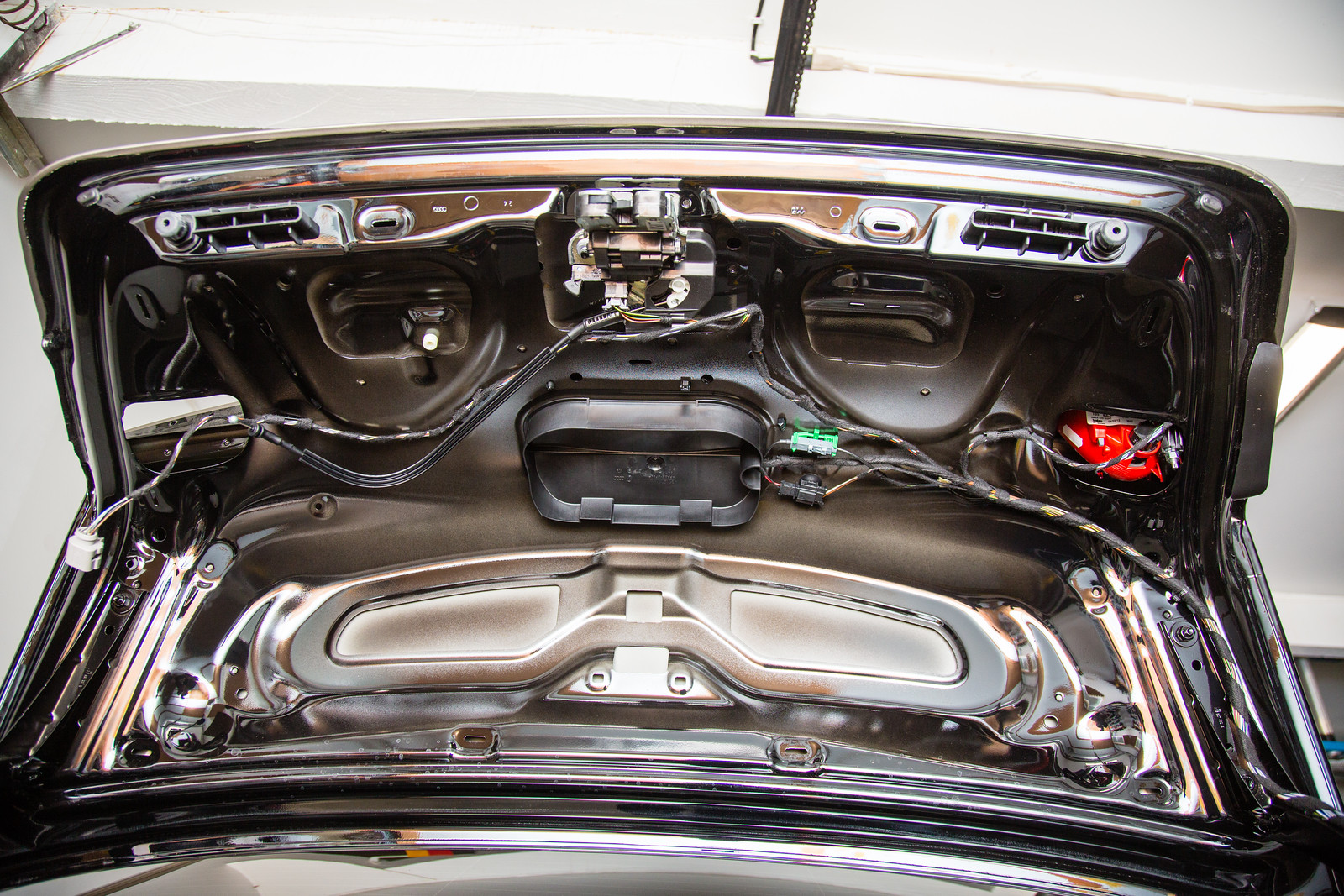
Trunk lid liner removed
Removing and preparing the tail lights
|
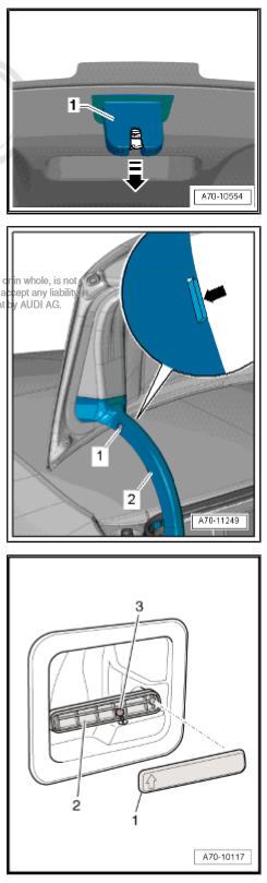
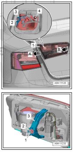
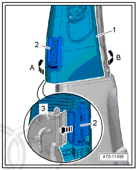
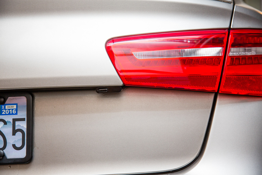
Removing the tail lights is fairly straight forward. Pop the trunk, and slide off the side cover for the tail lamp. Note the direction of the arrows to the right, and have faith it moves in that direction. A little patience will get you there.
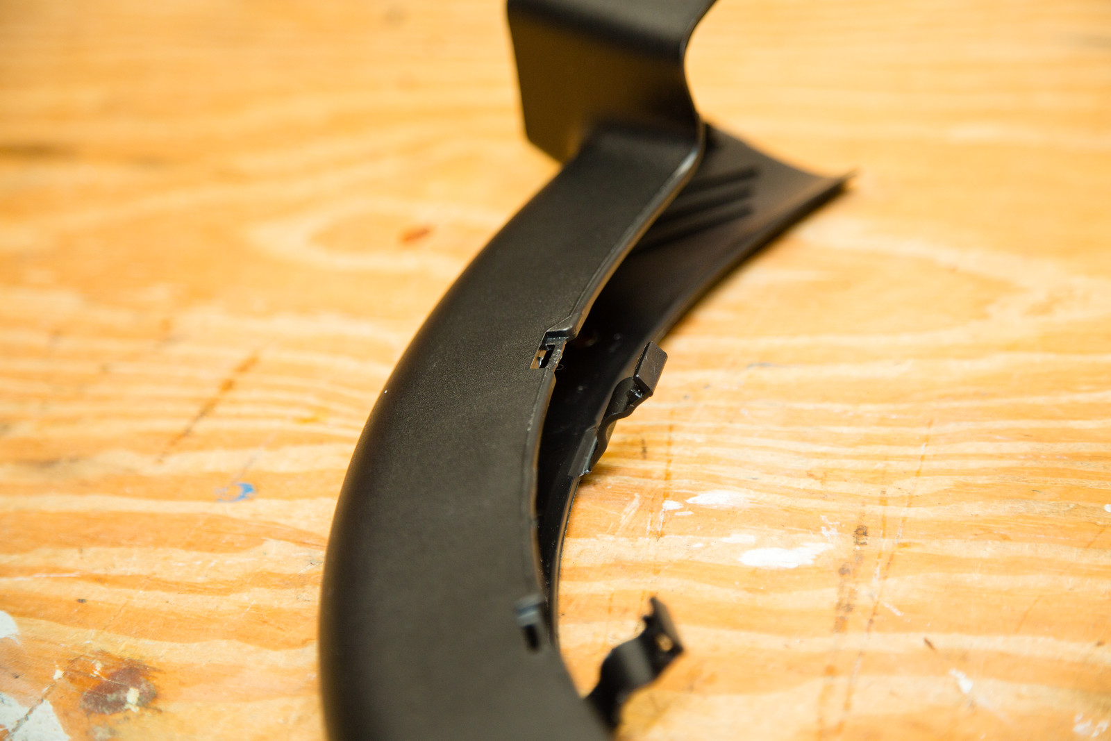
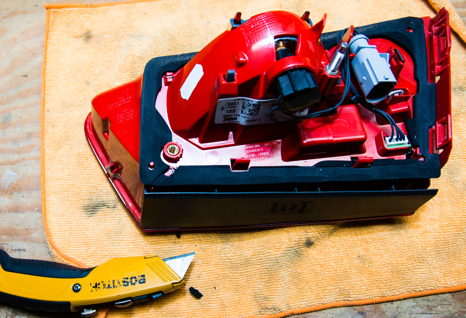
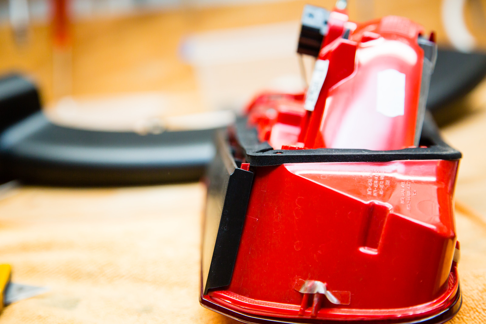
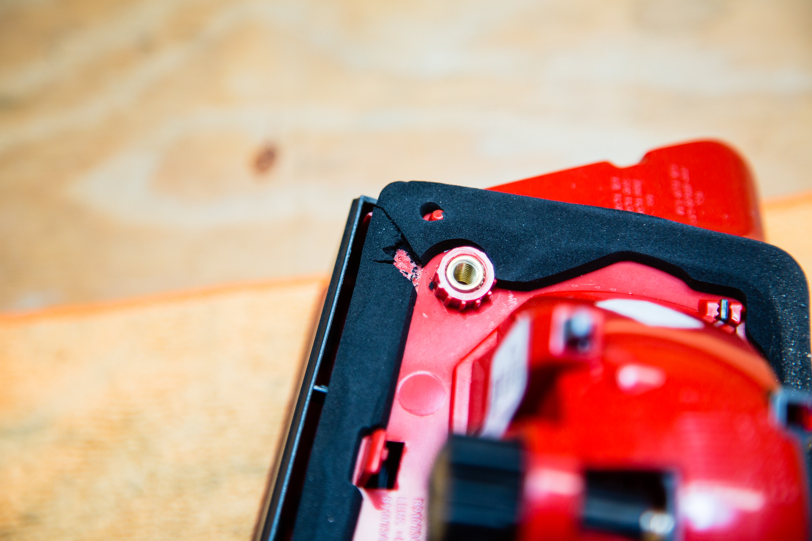
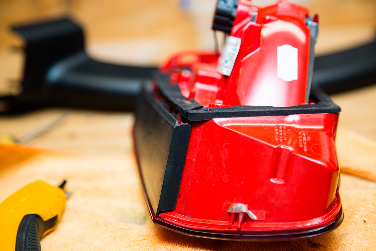
Next, remove the bolt that holds it into place (#2 to the right), disconnect the connector, and voila. Now it's time to prep it. In order to make sure the cable didn't get super squished when put between the trunk lid and tail light, I decided to cut out some of the foam surround. I cut away and tested to see if the tail light would get back to flush (I took before and after shots) without killing it in the process. I noticed that a little tab on the tail light would give a bit more room, too, so I dremel'ed that off. Full pics below.
|
|
Routing the sensor cables
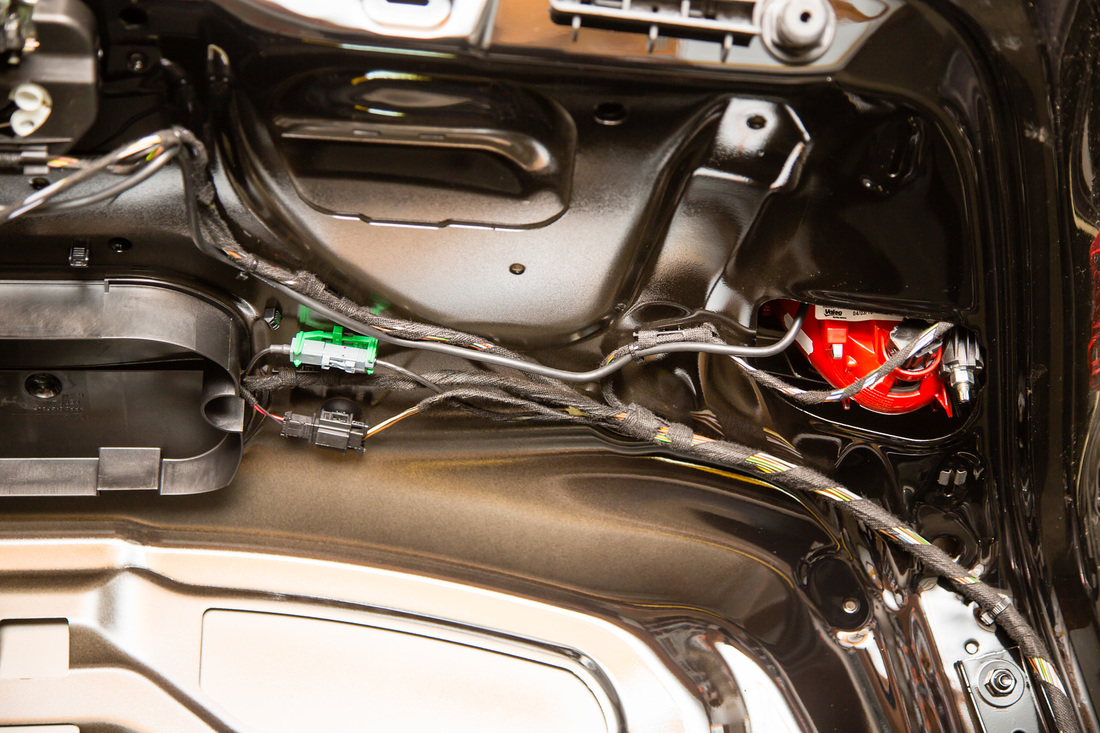
Note, I put green electrical tape on one of the extension cables and sensor cables (back right for me). Some on the ends, and also some along the way in case I ever needed to service one sensor run or the other I would know which cable is which. You'll also notice that one of the extensions joins to the sensor cable right on the rounded trunk lid 'connectors'. I was afraid the covers for this weren't going to fit, but it wasn't an issue at all. Finally, securing the cables to each other via small zip ties every 18 inches or so, and also to surrounding cables/hardware throughout the car makes sure they're not going anywhere.
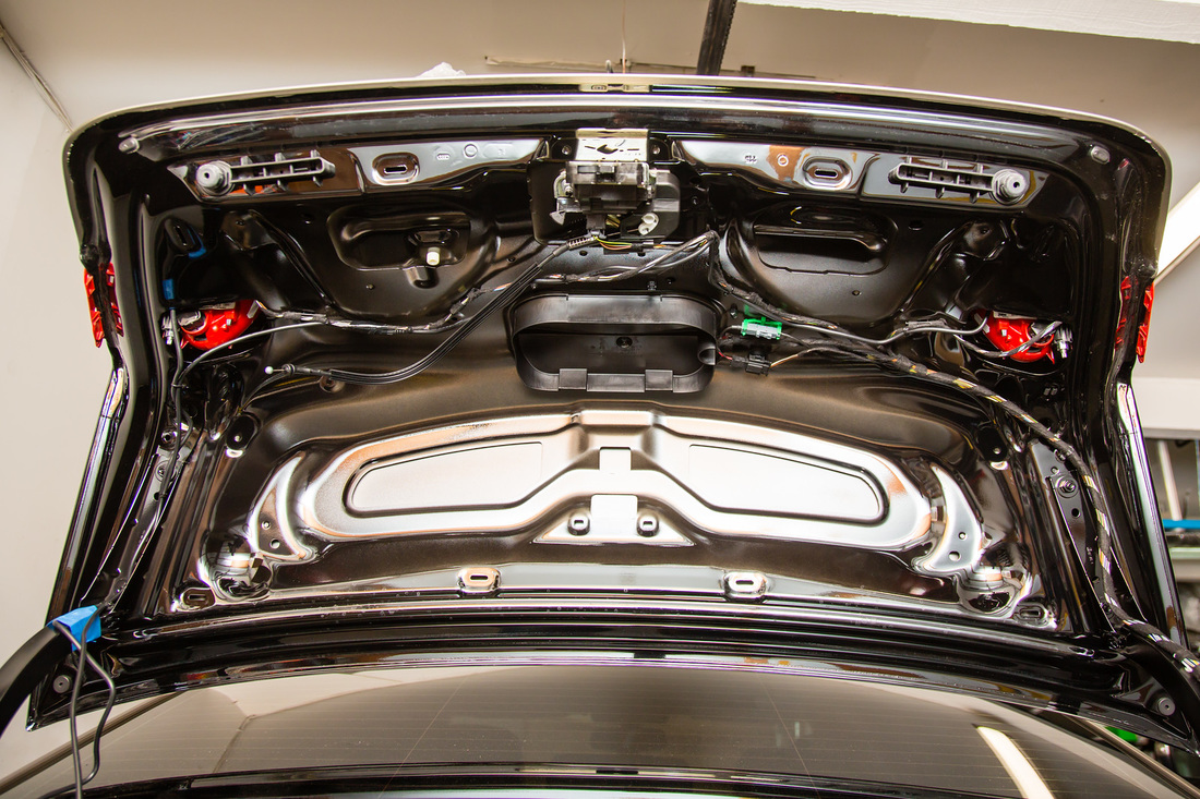
I mocked up the sensors where I wanted them to be and focused on running the cables next. No real rocket science as far as running the cables along the trunk lid, but I took a few moments to see where pressure points might be applied once the liner was put back in to make sure the cable wouldn't get smushed. Zip ties secured the cables to existing cable.
I mocked up the sensors where I wanted them to be and focused on running the cables next. No real rocket science as far as running the cables along the trunk lid, but I took a few moments to see where pressure points might be applied once the liner was put back in to make sure the cable wouldn't get smushed. Zip ties secured the cables to existing cable.
|
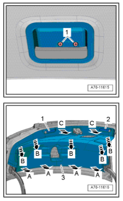
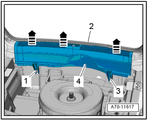
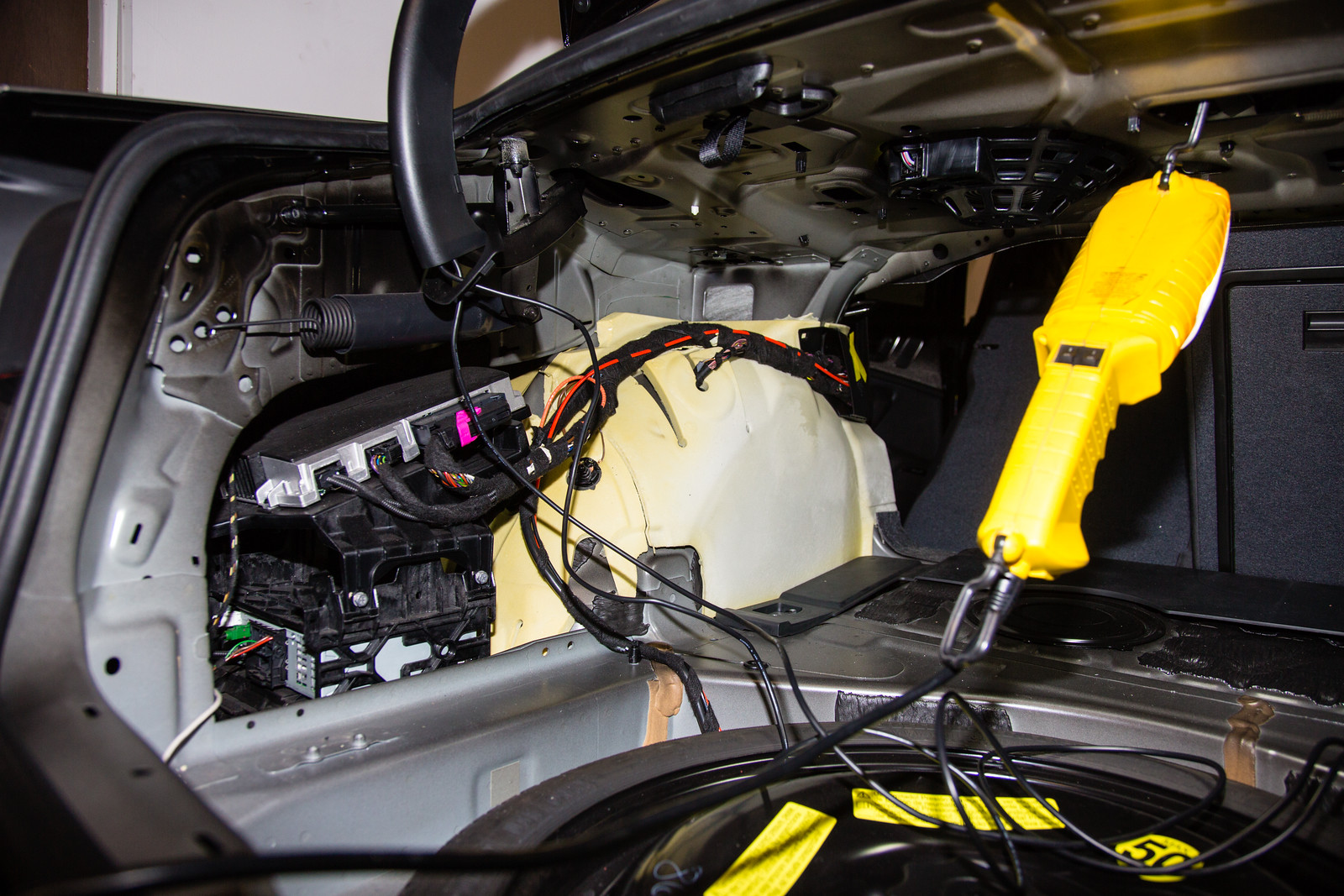
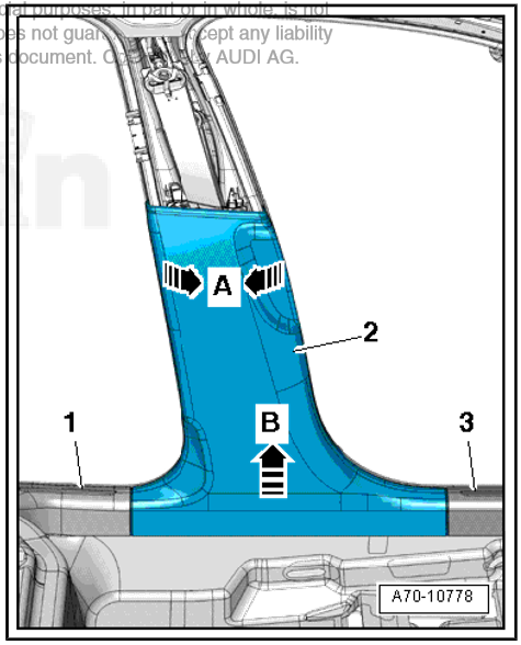
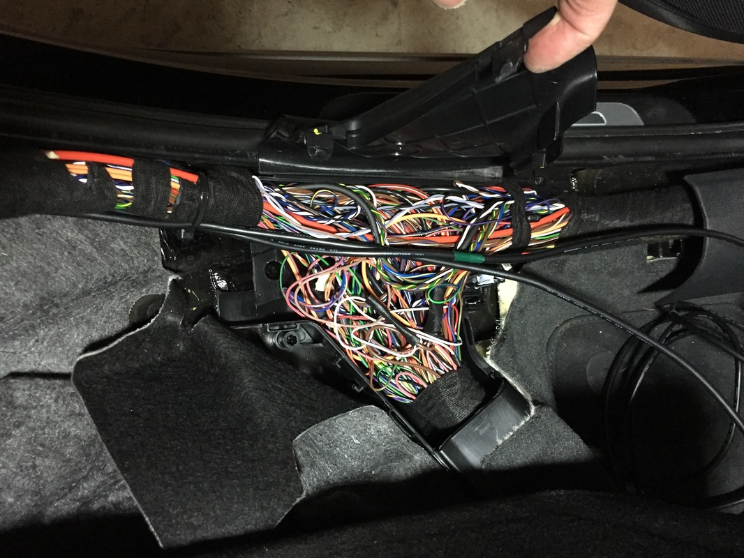
Next, the inside left trunk liner needed to be removed. A few things you need to do in order to get it off, none of them hard.
|
|
|
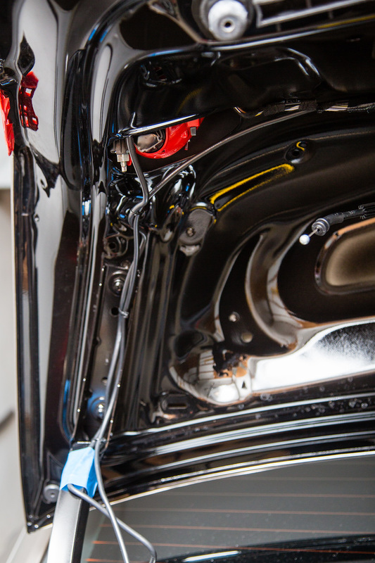
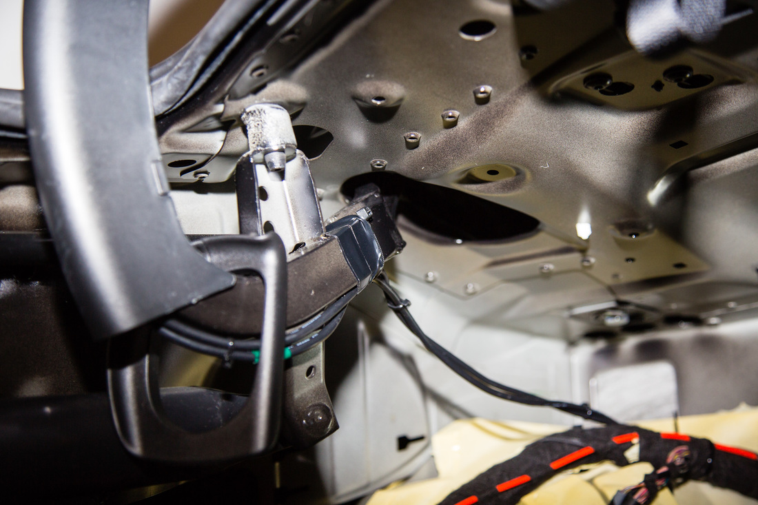
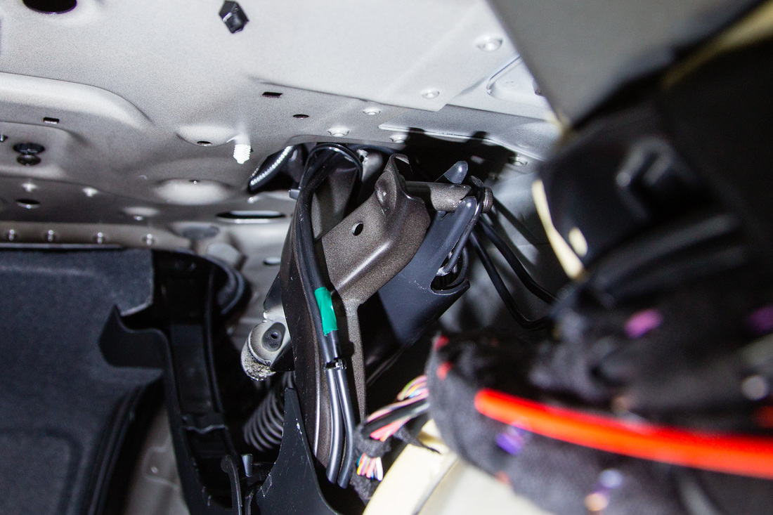
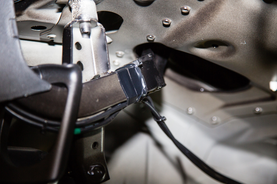
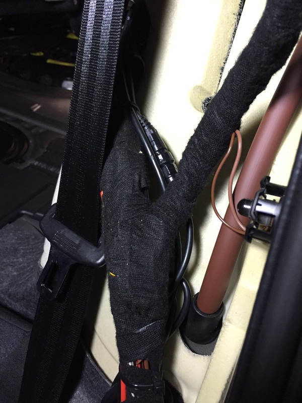
This is where I needed to redo things after my initial cable routing. Why? Because I forgot to think about the cables rubbing up against the inside of the removed trunk panel as the trunk opens and closes. On second attempt, I made sure to fully observe the cables during open and close to see if they bulged out at all towards the center of the trunk. Note how I secured the cables to the top of the moving piece. There's a chance they could hit at the top when the trunk is fully closed, but I avoided that. I used a zip tie and also electrical around that zip tie so the tie wouldn't slide down.
|
|
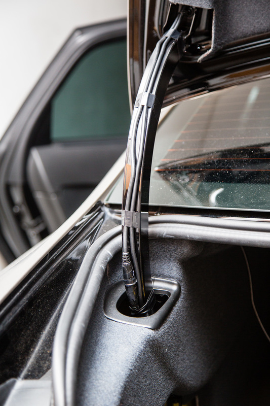
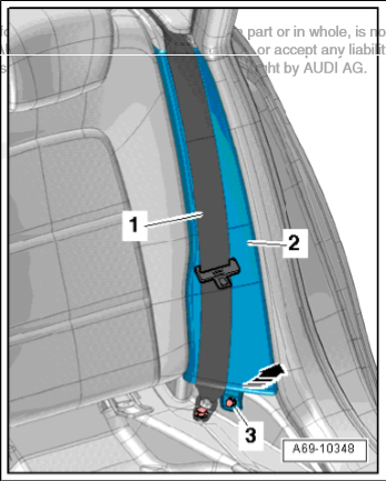
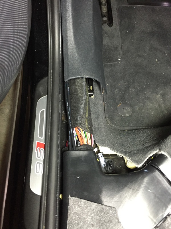
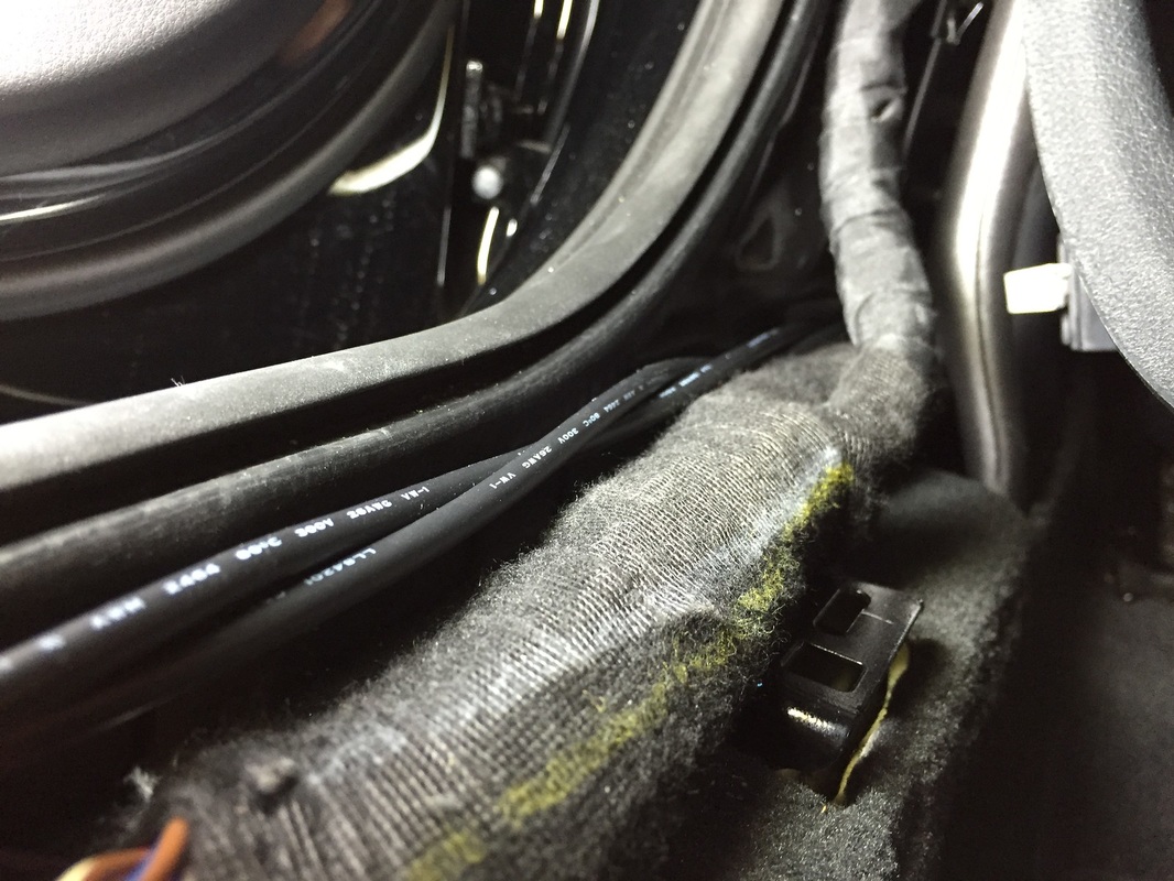
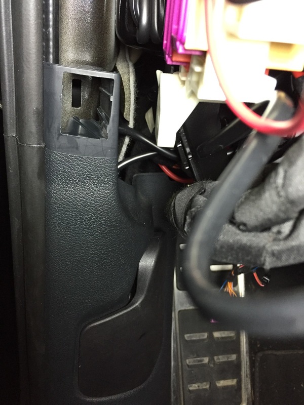
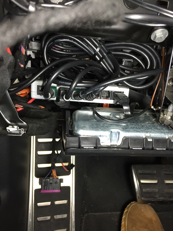
From there, it's just a matter of running it up the side of the car. It'll be easiest if you remove the various trim panels but potentially possible to just tuck it up underneath. I ran it down the side bolster area then forward alongside the existing wiring. Trim panel removal info below. Note that I did not fully remove the lower B panel, or the upper one. Just managed to loosen it a bit. Also, I didn't remove the front floor sill as I couldn't figure out how to get the hood latch release off. Decided I didn't want to mess with it so just battled a bit and squeezed the wires in between the trim and rubber seal. I did make sure they got all the way in where they don't have pressure on them.
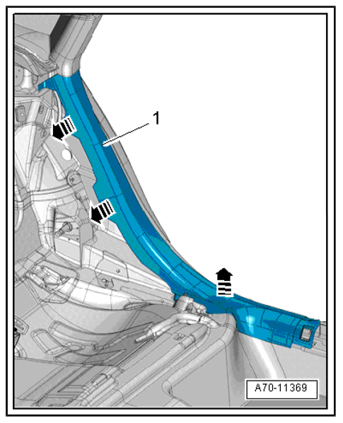
Once trim was removed, just needed to run the cables up...
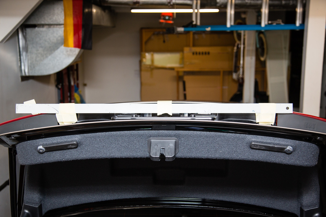
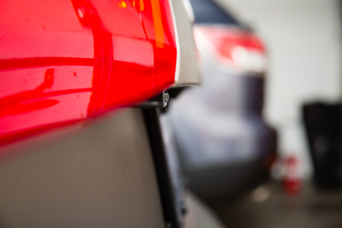
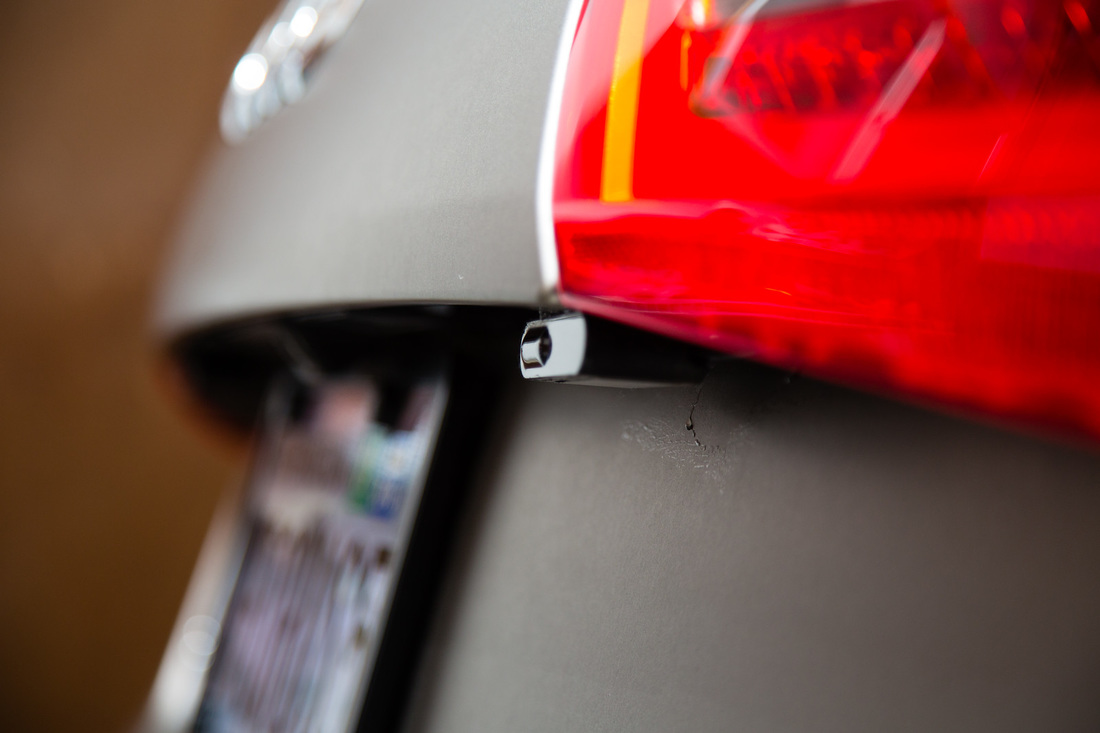
Final Step: Securing the sensors
Last but not least, it's time to level and secure the sensors. As I did with my Laser Interceptor setup on my RS4, I used silicone to secure the sensors. Why? Because it's the best at letting you do fine tune adjustments as the silicone hardens but isn't locked into place yet. With my prior test fitting, I knew I was putting it just to the inside of each of the tail lights. I held them into place and used the bubble level to see how I needed to adjust. I ended up putting a strip of 3M tape on the back and inside edges of the sensors to get them to as level as possible. To make sure I didn't angle them out or in, I used a long ruler that I then attached temporarily via tape between them, making sure the edges were directly up against the sensors. It's a foolproof way of making sure they're straight with each other. (Note: you need to wait a bit for the silicone to get harder to be able for it to stay in place by itself. I did use masking tape to hold them roughly in the right position throughout).
I know I could've moved them further out to the edge of the trunk lid, but wanted to try this somewhat recessed look first. Based on actual test results, I'd move them out if needed. Final shots below (some show wet areas around the sensors, that's just from a quick wipe down).
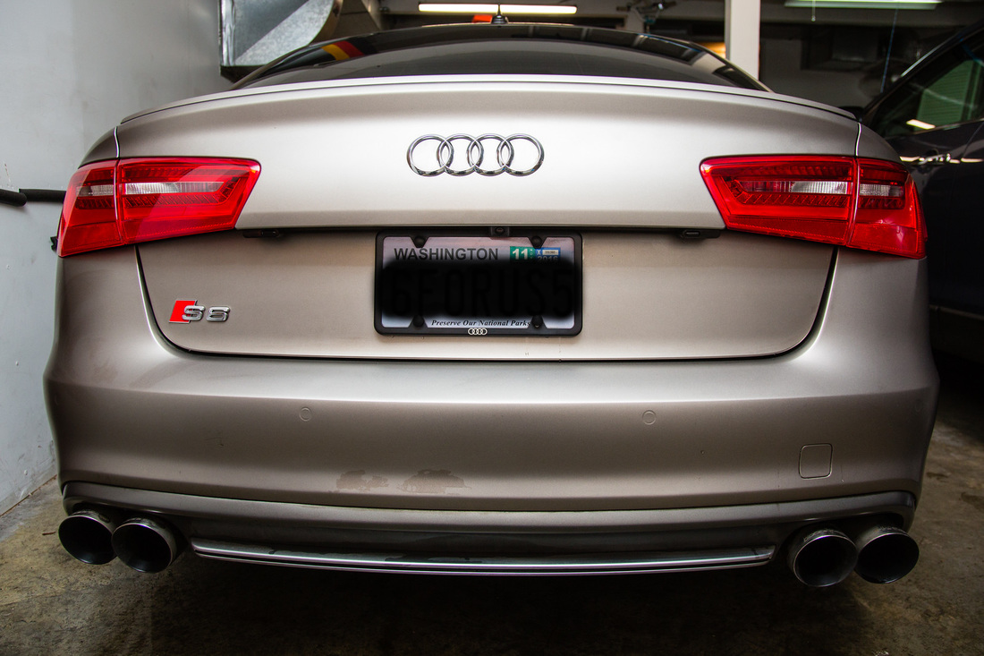
Thanks again to Vortex, we tested this setup shortly after I was done. We did our best to find areas that would simulate someone shooting lidar from an overpass, to see if recessing the sensors was going to lead to punch through's. We did our best, but the system retained its perfect record of jamming to gun at every attempt. Good stuff, and finally done! :)
